Certification track: Professional Cloud Architect (PCA) · Professional Cloud Network Engineer (PCNE)
Multi-Cluster Bank of Anthos on GKE
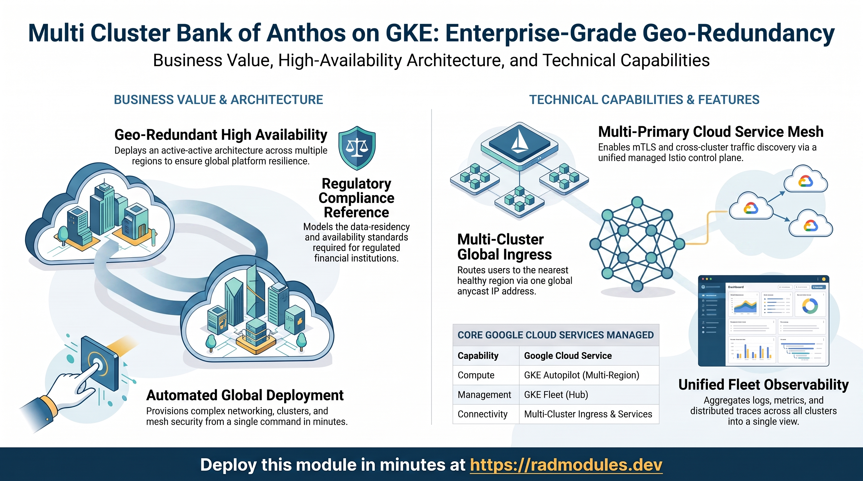
This module deploys Bank of Anthos — Google's open-source microservices banking demo — across multiple GKE clusters in multiple regions, wired together as a single application platform. It is a self-contained, standalone module: it builds its own VPC, creates every GKE cluster, registers them all into a GKE Fleet, joins them into one multi-primary Cloud Service Mesh, and fronts them with a multi-cluster gateway / global external load balancer so a single public address serves the nearest healthy region.
It is intended as an educational reference for the active-active, geo-redundant architecture that regulated financial and global payment platforms use to meet high-availability and data-residency requirements. It is not a production banking system.
This guide focuses on the Google Cloud services the module exercises and how to explore and operate them from the Cloud Console and the command line — with particular attention to working across more than one cluster at once.
1. Overview
The module stands up an entire multi-cluster platform from nothing and then deploys the banking application onto it:
| Capability | Google Cloud service | Notes |
|---|---|---|
| Compute | GKE Autopilot (Standard optional) | One cluster per region; cluster_size clusters, default 2 |
| Multi-cluster management | GKE Fleet (Hub) | Every cluster registered as a Fleet membership |
| Service mesh | Cloud Service Mesh (managed Istio) | Multi-primary, enabled fleet-wide in automatic-management mode |
| Cross-cluster discovery | Multi-Cluster Services (MCS) | Fleet feature for cross-cluster service backends |
| Global ingress | Multi-Cluster Ingress + global external Application Load Balancer | One anycast IP routes to the nearest healthy cluster |
| TLS | Google-managed certificate | Auto-provisioned for an sslip.io domain derived from the global IP |
| Networking | Shared VPC, per-cluster subnets, Cloud Router + Cloud NAT, firewall rules | Global-routing VPC; private nodes with NAT egress |
| Observability | Cloud Logging, Cloud Monitoring, Managed Service for Prometheus, Cloud Trace | Aggregated across the whole fleet |
| Application | Bank of Anthos (v0.6.7) | 9 microservices (Python + Java) plus two in-cluster PostgreSQL databases |
Things to know up front:
- This is genuinely multi-cluster.
cluster_size(default2) clusters are created and each is placed in a region fromavailable_regionsin round-robin order. With the defaults you get two clusters:gke-cluster-1inus-west1andgke-cluster-2inus-east1. Adding more regions or raisingcluster_sizespreads further (e.g. 2 regions + 4 clusters cyclesus-west1,us-east1,us-west1,us-east1). - Cluster names are 1-indexed —
gke-cluster-1,gke-cluster-2, …,gke-cluster-N.cluster1is always the primary / config cluster inavailable_regions[0]. - The databases live on the primary cluster only. The
accounts-dbandledger-dbPostgreSQL StatefulSets are deployed only ongke-cluster-1. Non-primary clusters run the stateless services plus the database Services and ConfigMaps, but not the database pods — they are designed to reach the primary cluster's databases through the fleet. Losing the primary cluster takes the data tier offline. - One global IP, one domain. A single global address is reserved and the app is published at
https://boa.<GLOBAL_IP>.sslip.io, with TLS issued automatically.sslip.ioresolves any<ip>.sslip.ioname to that IP, so no DNS zone is required. - The mesh is multi-primary. Cloud Service Mesh is enabled at the fleet level with automatic management; every cluster runs a managed control plane and shares one trust domain (
<project>.svc.id.goog), so sidecars in any cluster mutually authenticate. - No Cloud SQL, Memorystore, or Secret Manager are used by the app. Bank of Anthos runs its own in-cluster PostgreSQL and a Kubernetes-Secret JWT key pair. (Some related project APIs are enabled, but the application does not depend on those managed services.)
- First deploy is long. Creating multiple clusters, registering the fleet, provisioning the managed mesh, and bringing up the global load balancer with a managed certificate typically takes 40–60 minutes.
2. Google Cloud Services & How to Explore Them
Because this is a multi-cluster deployment, most exploration involves switching between cluster contexts. Set up one context per cluster and reuse them throughout:
export PROJECT="<your-project-id>"
export REGION1="us-west1"   # available_regions[0] — primary/config cluster
export REGION2="us-east1"   # available_regions[1]

gcloud container clusters get-credentials gke-cluster-1 --region "$REGION1" --project "$PROJECT"
gcloud container clusters get-credentials gke-cluster-2 --region "$REGION2" --project "$PROJECT"

# Friendlier context aliases
kubectl config rename-context "gke_${PROJECT}_${REGION1}_gke-cluster-1" cluster1
kubectl config rename-context "gke_${PROJECT}_${REGION2}_gke-cluster-2" cluster2
kubectl config get-contexts
The application namespace is bank-of-anthos on every cluster.
A. GKE clusters — the compute fabric
Each cluster runs the banking workloads on Autopilot (Standard is optional). Clusters are VPC-native, enrolled in the chosen release channel, and have GKE Security Posture, Managed Prometheus, the GCS FUSE CSI driver, Gateway API, and cost management enabled.
- Console: Kubernetes Engine → Clusters lists every cluster with its mode, region, version, and node count.
- CLI:
gcloud container clusters list --project "$PROJECT" \
  --format="table(name,location,autopilot.enabled,currentMasterVersion,status)"
kubectl --context cluster1 get nodes -o wide
kubectl --context cluster2 get nodes -o wide
B. GKE Fleet (Hub)
Every cluster is registered as a Fleet membership (membership ID = cluster name) under a single project-level fleet. The fleet is what makes the mesh, MCS, and Multi-Cluster Ingress span clusters.
- Console: Kubernetes Engine → Fleets shows all memberships and which fleet features are enabled per cluster.
- CLI:
gcloud container fleet memberships list --project "$PROJECT"
gcloud container fleet features list --project "$PROJECT"
C. Multi-Cluster Services (MCS)
MCS is enabled as a fleet feature so services can have backends across clusters. The frontend is published fleet-wide through a MultiClusterService (bank-of-anthos-mcs) on the config cluster.
- Console: Kubernetes Engine → Services & Ingress (on the config cluster) shows the multi-cluster Service.
- CLI:
kubectl --context cluster1 get multiclusterservice -n bank-of-anthos
kubectl --context cluster1 describe multiclusterservice bank-of-anthos-mcs -n bank-of-anthos
# The MCS importer runs in the gke-mcs namespace on member clusters:
kubectl --context cluster2 get pods -n gke-mcs
D. Cloud Service Mesh (multi-primary)
The mesh is enabled fleet-wide with automatic management — Google runs the Istio control plane for each cluster. The bank-of-anthos namespace carries istio.io/rev=asm-managed, so every pod gets an Envoy sidecar (each app pod shows 2/2 ready). All clusters share one trust domain, so the mesh is multi-primary and traffic between clusters is mutually authenticated.
- Console: Kubernetes Engine → Service Mesh shows the combined topology, golden signals, and mTLS status across all clusters.
- CLI:
gcloud container fleet mesh describe --project "$PROJECT"   # per-membership control/data plane state
# Confirm sidecar injection on each cluster:
kubectl --context cluster1 get pods -n bank-of-anthos
kubectl --context cluster2 get pods -n bank-of-anthos
# Inspect the SPIFFE identity in a sidecar's certificate:
POD=$(kubectl --context cluster1 get pod -n bank-of-anthos -l app=frontend -o jsonpath='{.items[0].metadata.name}')
kubectl --context cluster1 exec "$POD" -n bank-of-anthos -c istio-proxy -- \
  cat /var/run/secrets/workload-spiffe-credentials/certificates.pem \
  | openssl x509 -noout -text | grep -E "URI:"
E. Multi-cluster gateway & global load balancing
A single global IP is reserved and a MultiClusterIngress (bank-of-anthos-mci) on the config cluster provisions a global external Application Load Balancer whose backends span every cluster. Google's network routes each user to the nearest healthy cluster. TLS is terminated at the load balancer using a Google-managed certificate for boa.<GLOBAL_IP>.sslip.io, and an HTTP→HTTPS (301) redirect is enforced.
- Console: Network Services → Load balancing shows the global load balancer, its frontends, the backend service, and the health of each per-cluster Network Endpoint Group.
- CLI:
gcloud compute addresses list --global --project "$PROJECT" --filter="name~bank"
kubectl --context cluster1 get multiclusteringress -n bank-of-anthos
kubectl --context cluster1 get managedcertificate -n bank-of-anthos \
  -o jsonpath='{range .items[*]}{.metadata.name}{"\t"}{.status.certificateStatus}{"\n"}{end}'
# Backend health per cluster NEG:
BACKEND=$(gcloud compute backend-services list --global --project "$PROJECT" \
  --filter="name~bank-of-anthos" --format="value(name)" | head -1)
gcloud compute backend-services get-health "$BACKEND" --global --project "$PROJECT"
F. Networking (VPC, NAT, firewall)
All clusters share one global-routing VPC. Each cluster gets its own subnet with secondary ranges for pods and services, a Cloud Router + Cloud NAT for private egress, a reserved static external IP, and a set of firewall rules (internal traffic, the GKE control plane, load-balancer health checks, and the ASM webhook ports).
- Console: VPC network → VPC networks → the deployment's network; VPC network → Firewall.
- CLI:
gcloud compute networks subnets list --project "$PROJECT" \
  --format="table(name,region,ipCidrRange)"
gcloud compute firewall-rules list --project "$PROJECT" \
  --format="table(name,direction,allowed[].map().firewall_rule().list())"
G. Observability (Logging, Monitoring, Prometheus, Trace)
Pod logs flow to Cloud Logging; GKE and mesh metrics flow to Cloud Monitoring and Managed Prometheus; the mesh sends distributed traces to Cloud Trace. All of this aggregates across the fleet, so you can compare clusters side by side.
- Console: Logging → Logs Explorer; Monitoring → Dashboards (GKE group); Kubernetes Engine → Service Mesh for golden signals.
- CLI:
gcloud logging read \
  'resource.type="k8s_container" AND resource.labels.namespace_name="bank-of-anthos"' \
  --project "$PROJECT" --limit 20 \
  --format="table(timestamp,resource.labels.cluster_name,resource.labels.location)"
kubectl --context cluster1 top pods -n bank-of-anthos
kubectl --context cluster2 top pods -n bank-of-anthos
H. The Bank of Anthos application
Bank of Anthos is a retail-banking simulation: sign up, log in, view balances, and transfer funds. It comprises a frontend, userservice, contacts, ledgerwriter, balancereader, transactionhistory, a loadgenerator (continuous synthetic traffic), and the accounts-db / ledger-db PostgreSQL databases. The load generator keeps traffic flowing so the mesh dashboards and traces show live data immediately. Authentication uses a JWT key pair stored as the jwt-key Kubernetes Secret.
- Console: Kubernetes Engine → Workloads (filter by the
bank-of-anthosnamespace), per cluster. - CLI:
kubectl --context cluster1 get deploy,statefulset,svc -n bank-of-anthos
kubectl --context cluster2 get deploy,statefulset,svc -n bank-of-anthos   # note: no DB StatefulSets here
3. Behaviour
What gets deployed on apply. The module enables the required project APIs, creates (or reuses) the shared VPC and per-cluster subnets/NAT/firewalls, then creates cluster_size GKE clusters across the chosen regions. Each cluster is registered into the fleet and the module waits for every membership to reach READY (polled up to ~10 minutes) before continuing. If the mesh is enabled, it is turned on at the fleet level and per membership in automatic-management mode, and the module waits for the mesh to configure on each cluster.
Application rollout across clusters. With deploy_application = true, the module downloads the pinned Bank of Anthos release (v0.6.7), creates the bank-of-anthos namespace (labelled for sidecar injection) on each cluster, applies the JWT secret, and applies the workload manifests:
- On the primary cluster (
cluster1) the full manifest set is applied, including theaccounts-dbandledger-dbStatefulSets. - On every other cluster the same manifests are applied but the database StatefulSets are stripped out — the stateless services and the database Services/ConfigMaps are still created so other pods can resolve them, and they are designed to use the databases on the primary cluster across the fleet. Any pre-existing DB StatefulSets on non-primary clusters are removed.
The module waits for deployments to become available on each cluster before reporting success.
Global ingress. After the app is running, the module enables the Multi-Cluster Ingress fleet feature (config cluster = cluster1) and applies, on the config cluster, the MultiClusterService (frontend backends across clusters), the MultiClusterIngress (the global load balancer), a NodePort service + BackendConfig (load-balancer health checks), the managed certificate for boa.<GLOBAL_IP>.sslip.io, the FrontendConfig (HTTPS redirect), and a mesh telemetry ConfigMap in istio-system. Traffic then flows: user → global anycast IP → nearest healthy cluster's NEG → frontend pod (Envoy sidecar) → downstream services over mesh mTLS.
Manual follow-up. The Google-managed certificate provisions asynchronously and can take 10–60 minutes to become Active; until then HTTPS may warn or fail. Use the demo credentials shown on the Bank of Anthos sign-in page to log in. To enable CDN, custom domains, IAP, or cross-cluster traffic policies (VirtualService/DestinationRule), apply the relevant Kubernetes resources after deployment.
Runtime notes. Each app pod runs 2/2 (app + sidecar). The mesh shares one trust domain, so cross-cluster calls are mutually authenticated. Because the data tier lives only on the primary cluster, scaling the primary to zero or losing its region affects the databases — the stateless frontends on other clusters stay reachable through the global load balancer but depend on the primary for data.
Destroy. Tear-down runs ordered cleanup steps that remove the Multi-Cluster Ingress/Service resources, disable the mesh and Multi-Cluster Ingress fleet features, unregister fleet memberships, and delete leftover MCS firewall rules and NEGs before removing the clusters and VPC. APIs enabled by the module are left enabled to avoid disrupting other workloads.
4. Configuration Variables
Variables are grouped exactly as they appear on the deployment platform.
Group 1 — Project & Regions
| Variable | Default | Description |
|---|---|---|
project_id | (required) | Target Google Cloud project. Must already exist. |
available_regions | ["us-west1", "us-east1"] | Regions clusters are placed into, round-robin by cluster index. If fewer regions than clusters, regions are cycled. Must have at least one entry. |
Group 2 — Network
| Variable | Default | Description |
|---|---|---|
create_network | true | Create a new shared VPC for all clusters. Set false to use an existing network named by network_name. |
network_name | vpc-network | Name of the shared VPC. When creating, a unique suffix is appended automatically. |
subnet_name | vpc-subnet | Base name for per-cluster subnets (<subnet_name>-cluster<N>). Used only when create_network = true. |
Group 3 — GKE Clusters
| Variable | Default | Description |
|---|---|---|
create_autopilot_cluster | true | Create Autopilot clusters (fully managed nodes). Set false for Standard clusters with managed node pools. Applies to all clusters. |
release_channel | REGULAR | GKE release channel for all clusters: RAPID, REGULAR, STABLE, or NONE. |
cluster_size | 2 | Number of GKE clusters to create. Minimum 2 for a meaningful multi-cluster demo; upper bound limited by regional quota. |
Group 4 — Service Mesh
| Variable | Default | Description |
|---|---|---|
enable_cloud_service_mesh | true | Install and configure Cloud Service Mesh (managed Istio) fleet-wide for mTLS, cross-cluster traffic, and unified observability. |
cloud_service_mesh_version | 1.23.4-asm.1 | Mesh version to install (major.minor.patch-asm.N). Used only when the mesh is enabled; must be compatible with the cluster versions/channel. |
Group 5 — Application
| Variable | Default | Description |
|---|---|---|
deploy_application | true | Deploy Bank of Anthos across all clusters after they are created. Set false to provision cluster infrastructure only. |
5. Outputs
| Output | Description |
|---|---|
deployment_id | The deployment ID (provided or auto-generated) used to suffix resource names. |
project_id | The target project ID. |
The application's public address is not exposed as a Terraform output. Retrieve the global IP from the reserved global address (
gcloud compute addresses list --global --filter="name~bank") or theMultiClusterIngressstatus, then browse tohttps://boa.<GLOBAL_IP>.sslip.io.
6. Configuration Pitfalls & Sensible Defaults
Risk: Critical (data loss / outage / security) — High (service degraded) — Medium (cost or partial degradation) — Low (minor).
| Setting | Sensible value | Risk | Consequence if wrong |
|---|---|---|---|
cluster_size | 2 (or more) | High | Setting 1 defeats the purpose — no multi-cluster ingress, mesh span, or failover. Very large values can exhaust regional quota and fail mid-apply. |
available_regions | ≥ 2 distinct regions | High | A single region removes geo-redundancy; all clusters share one region's failure domain. |
Primary cluster (cluster1) | treat as the data tier | Critical | The accounts-db / ledger-db databases run only on the primary cluster. Losing its region, or scaling it to zero, takes the data tier offline for every cluster. |
deployment_id | set once, then leave | Critical | Changing it after first deploy forces recreation of named resources (VPC, clusters), destroying running state. |
cloud_service_mesh_version | a version matching the cluster channel | High | An incompatible mesh version can leave the managed control plane unconfigured and sidecars uninjected. |
create_network / network_name | true for a fresh project | Medium | Pointing at a non-existent or overlapping existing network (when false) breaks subnet and cluster creation. |
| Managed certificate wait | allow 10–60 min | Medium | Browsing https://boa.<IP>.sslip.io before the certificate is Active shows TLS warnings or failures — expected during provisioning, not a deployment error. |
create_autopilot_cluster | true | Low | Standard clusters add node-pool management and per-node cost; Autopilot is simpler and cheaper for this demo. |
enable_cloud_service_mesh | true | Medium | Disabling it removes mTLS, cross-cluster traffic management, and the Service Mesh observability the module is built to demonstrate. |
| First-deploy time | budget 40–60 min | Low | Multi-cluster + fleet + managed mesh + global LB provisioning is inherently slow; do not assume a stall. |
This is a standalone, educational module that builds its own VPC, clusters, fleet, mesh, and global load balancer — it does not depend on a separate foundation module. For the upstream application, see the Bank of Anthos repository.